Purpose
The RT6204 is a 60V, 500mA, 350kHz, high-efficiency, synchronous step-down DC-DC converter with an input-voltage range of 5.2V to 60V and a programmable output-voltage range of 0.8V to 50V. This document explains the function and usage of the RT6204GSP evaluation board (EVB), and provides information for power-up operation, and the modification of the evaluation board and the circuit, to be suitable for individual requirements.
Introduction
General Product Information
The RT6204 is a 60V, 500mA, 350kHz, high-efficiency, synchronous step-down DC-DC converter with an input-voltage range of 5.2V to 60V and a programmable output-voltage range of 0.8V to 50V. It features current-mode control to simplify external compensation and to optimize transient response with a wide range of inductors and output capacitors. High efficiency can be achieved through integrated N-MOSFETs, and pulse-skipping mode at light loads. With EN pin, power-up sequence can be more flexible and shutdown quiescent current can be reduced to <3µA.
The RT6204 features cycle-by-cycle current limit for over-current protection against short-circuit outputs, and user-programmable soft-start time to prevent inrush current during startup. It also includes input under-voltage lockout, output under-voltage, and thermal shutdown protection to provide safe and smooth operation in all operating conditions.
The RT6204 is available in the SOP-8 (Exposed pad) package.
Product Features
-
0.8V Feedback Reference Voltage with ±1.5% Accuracy
-
Wide Input Voltage Range : 5.2V to 60V
-
Output Current : 500mA
-
Integrated N-MOSFETs
-
Current-Mode Control
-
Fixed Switching Frequency : 350kHz
-
Programmable Output Voltage : 0.8V to 50V
-
Low <3µA Shutdown Quiescent Current
-
Up to 92% Efficiency
-
Pulse-Skipping Mode for Light-Load Efficiency
-
Programmable Soft-Start Time
-
Cycle-by-Cycle Current Limit Protection
-
Input Under-Voltage Lockout, Output Under-Voltage and Thermal Shutdown Protection
Key Performance Summary Table
|
Key Features
|
Evaluation Board Number : PCB073_V2
|
|
Input Voltage Range
|
5.2V to 60V
|
|
Max Output Current
|
500mA
|
|
Default Output Voltage
|
5V
|
|
Default Marking & Package Type
|
RT6204GSP, SOP-8 (Exposed pad)
|
|
Operation Frequency
|
Fixed 350kHz
|
Bench Test Setup Conditions
Headers Description and Placement
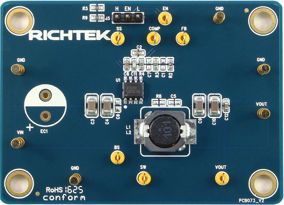
Carefully inspect all the components used in the EVB according to the following Bill of Materials table, and then make sure all the components are undamaged and correctly installed. If there is any missing or damaged component, which may occur during transportation, please contact our distributors or e-mail us at evb_service@richtek.com.
Test Points
The EVB is provided with the test points and pin names, listed in the table below.
|
Test Point/
Pin Name
|
Signal Name
|
Description
|
|
VIN
|
Input Voltage
|
Supply voltage input, 5.2V to 60V. Bypass VIN to GND with a large high-quality capacitor.
|
|
EN
|
Enable
|
Enable control input. A logic High (VEN > 1.35V) enables the device, and a logic Low (VEN < 0.925V) shuts down the device.
|
|
GND
|
Ground
|
Power ground. The exposed pad must be connected to GND and well soldered to the input and output capacitors and a large PCB copper area for maximum power dissipation.
|
|
SS
|
Soft-Start Control
|
Soft-start capacitor connection node. Connect an external capacitor from SS to GND to set the soft-start time. Do not leave SS pin unconnected. A capacitor of capacitance from 10nF to 100nF is recommended.
|
|
BS
|
Bootstrap Supply
|
Bootstrap capacitor connection node for high-side gate driver. Connect a 0.1μF ceramic capacitor from BOOT to SW to power the internal gate driver.
|
|
SW
|
Switch Node
|
Switch node for output inductor connection.
|
|
FB
|
Feedback Voltage Input
|
Feedback voltage input. Connect FB to the midpoint of the external feedback resistor divider to sense the output voltage. The device regulates the FB voltage at 0.8V (typical) Feedback Reference Voltage.
|
|
COMP
|
Compensation Node
|
Compensation node for the compensation of the regulation control loop. Connect a series RC network from COMP to GND. In some cases, another capacitor from COMP to GND may be required.
|
Power-Up & Measurement Procedure
1. Apply a 36V nominal input power supply (VIN < 60V) to the VIN and GND terminals.
2. Set the jumper at J5 to connect terminals 1 and 2, connecting EN to enable operation.
3. Verify the output voltage (approximately 5V) between VOUT and GND.
4. Connect an external load up to 500mA to the VOUT and GND terminals and verify the output voltage and current.
Output Voltage Setting
Set the output voltage with the resistive divider (R2, R3) between VOUT and GND with the midpoint connected to FB. The output voltage can be set by the following equation :

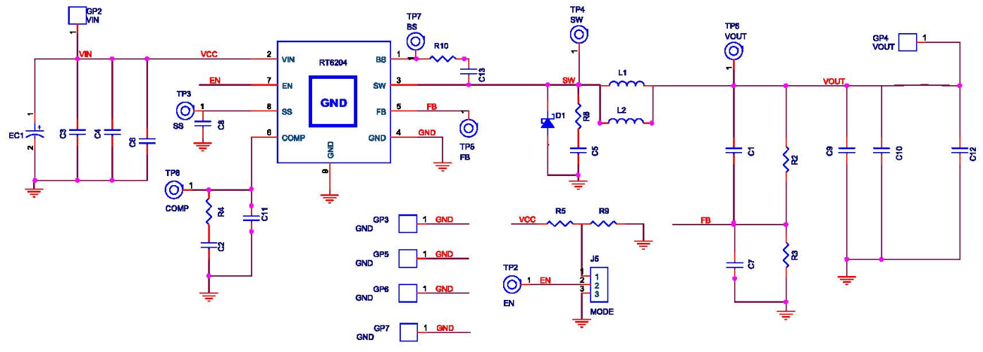
Schematic, Bill of Materials, & Board Layout
EVB Schematic Diagram
Bill of Materials
|
Reference
|
Qty
|
Part Number
|
Description
|
Package
|
Manufacturer
|
|
U1
|
1
|
RT6204GSP
|
DC-DC Converter
|
SOP-8 (Exposed pad)
|
RICHTEK
|
|
C2
|
1
|
0603B682K500
|
6.8nF/50V/X7R
|
C-0603
|
WALSIN
|
|
C8, C12, C13
|
3
|
C1608X7R1H104KT000N
|
0.1µF/50V/X7R
|
C-0603
|
TDK
|
|
C3, C4
|
2
|
GRM31CR72A225KA73L
|
2.2µF/100V/X7R
|
C-1206
|
MURATA
|
|
C9, C10
|
2
|
C3216X5R1H106KT000N
|
10µF/50V/X5R
|
C-1206
|
TDK
|
|
C11
|
1
|
0603N470J500
|
47pF/50V/NPO
|
C-0603
|
WALSIN
|
|
L1
|
1
|
7447714101
|
100µH/1.5A
|
10x10x5 (mm)
|
Wurth
|
|
R2
|
1
|
|
52.3k
|
R-0603
|
|
|
R3
|
1
|
|
10k
|
R-0603
|
|
|
R4
|
1
|
|
24k
|
R-0603
|
|
|
R5, R9
|
2
|
|
100k
|
R-0603
|
|
|
R10
|
1
|
|
0
|
R-0603
|
|
|
R8, C1, C5, C6, C7, EC1, D1, L2
|
8
|
|
NC
|
|
|
PCB Layout
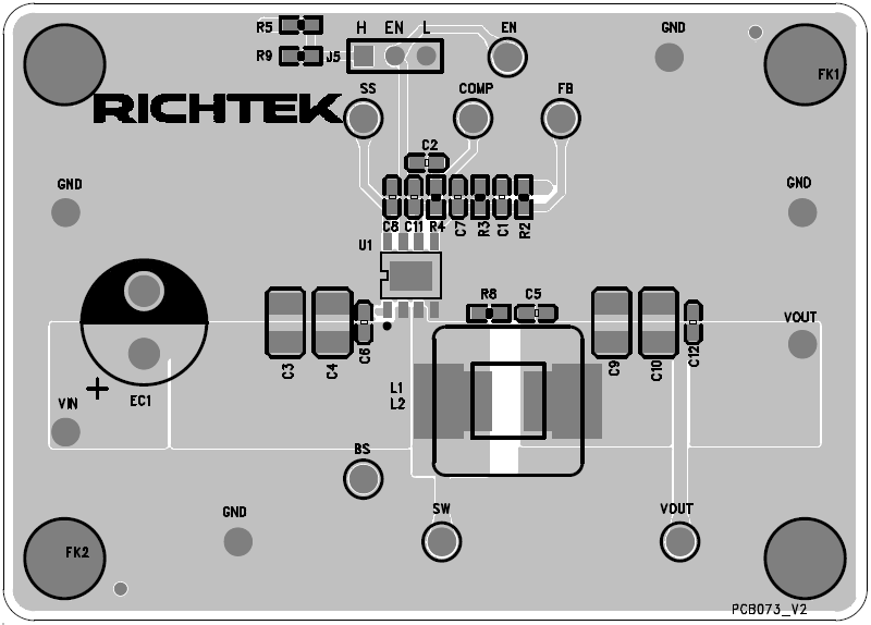
Top View
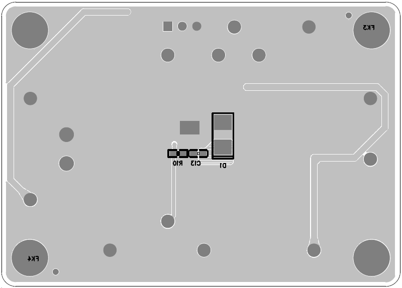
Bottom View